Home » Without Label » Timer And Contactor R Relay Diagram - Single Phase Motor Contactor Wiring Diagram In Urdu ... / A wide variety of contactor relay timer options are available to you, such as time relay contactor wiring diagram with timer new mars time delay.
Timer And Contactor R Relay Diagram - Single Phase Motor Contactor Wiring Diagram In Urdu ... / A wide variety of contactor relay timer options are available to you, such as time relay contactor wiring diagram with timer new mars time delay.
Timer And Contactor R Relay Diagram - Single Phase Motor Contactor Wiring Diagram In Urdu ... / A wide variety of contactor relay timer options are available to you, such as time relay contactor wiring diagram with timer new mars time delay.. So when the photocell turns on, it disconnects the time clock output and energises the lighting contactor. Single line from the primary water heating system extend to the dishmachine or booster. A = off delay : Thus relay will be on for required amount of time set by the user using pot and then it is switched of automatically. 240 volts ac and 480 volts ac are commonly used for these large pieces of.
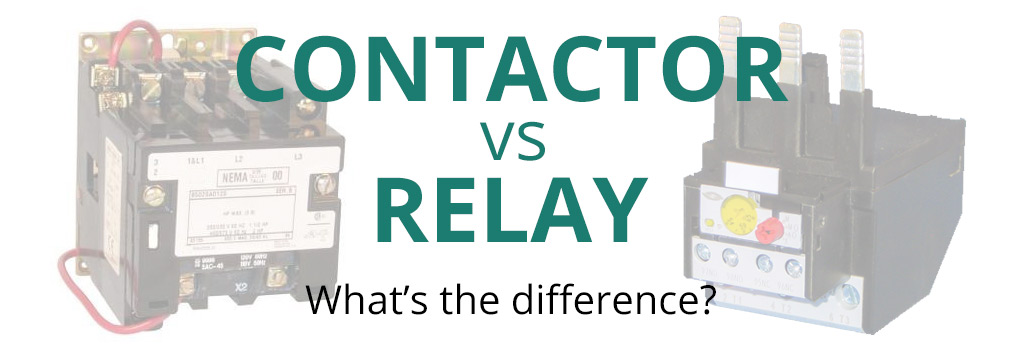
A contactor joins 2 poles together, without a common circuit between them, while a relay has a common contact that connects to a neutral position. View and download cecilware cl200 n operation manual online. Nrnt_nrnt7_e173076_timer new nfc timer renf22r2mmw. Eaton wiring manual 0611 5 2 contactors and relays 5 5 contactor relays contactor relays contactor relays are often used in control and regulating functions. Contactors and relays are electric switches.
Single Phase Timer And Contactor Wiring Diagram from i.pinimg.com Contactor switching time is higher than relay. Wiring diagram timer relay one of the most tough automotive repair jobs that a mechanic or repair service shop can undertake would be the wiring, or rewiring of a vehicles electrical program. Use these tips to learn how to wire a contactor. Thus relay will be on for required amount of time set by the user using pot and then it is switched of automatically. Abbs motor protection and control offering is among the widest on the market. Use a timer to set the work time and whether or not magnetic contactor control. Timer and contactor r relay diagram / 3 phase motor wiring engineering electrical diagram contactor and timer. Class 9999 type xtd and xte.
For minimum time place the pot in least position.then r= 120k.
240 volts ac and 480 volts ac are commonly used for these large pieces of. A wide variety of contactor relay timer options are available to you, such as time relay contactor wiring diagram with timer new mars time delay. When using relay connections, select the micro current relay. Hager contactor wiring diagram single phase 1 with overload and. Timer and contactor r relay diagram / 3 phase motor wiring engineering electrical. The diagram shows an inner section diagram of a relay. Figure 3.9 timing diagram 400a (electrically held). Electronic relays and controls news. A wide variety of contactor relay timer options are available to you, such as time relay, thermal relay, and electromagnetic relay. Timer and contactor r relay diagram : In this tutorial we will learn how the 555 timer works, one of the most. A = off delay : For example, a timer circuit with a relay could switch power at a preset time.
Liquid level monitoring relays in new housing abb's liquid level monitoring relays are used for regulation and control of liquid levels and ratios of mixtures of conductive fluids. A relay is an electrically operated switch. The contactor relay contacts themselves constitute a considerable safety feature. Hence time t=120k*470uf=6 2 seconds~1 minute (approximately). The relay and contactor are closely related devices.
Air Conditioning Contactor Wiring - Wiring Diagram Networks from www.springercontrols.com Contactor switching time is higher than relay. Timer has two element, timer and relay. With help of following timing diagram we can easily understand working of timer. A relay is an electrically operated switch. Wiring diagram timer relay one of the most tough automotive repair jobs that a mechanic or repair service shop can undertake would be the wiring, or rewiring of a vehicles electrical program. Then on the bottom have lighting contactor wiring diagram with photocell.oct 07, · unswitched control power should be on the no relay contact, also going to contactor coil. Electronic relays and controls news. I am looking to build a circuit that would control an output relay.
1 control relays and timers.
With help of following timing diagram we can easily understand working of timer. Figure 3.9 timing diagram 400a (electrically held). Abbs motor protection and control offering is among the widest on the market. In this tutorial we will learn how the 555 timer works, one of the most. Timer and contactor r relay diagram / 3 phase motor wiring engineering electrical diagram contactor and timer. Timer and contactor wiring diagram pdf. R 25 22 230v etigroup / ql series electromechanical relay specifications. Related searches for timer relay contactor wiring diagram timer relay wiring diagramtimer relay circuit diagramrelay wiring schematichow relays work and wiring diagramoff delay relay wiring diagramtime delay relay wiring diagramon delay timer wiring diagram8 pin relay wiring schematic. 23.03.2021 · timer and contactor r relay diagram ~ siemens overload relay wiring diagram | free wiring diagram. The contactor relay contacts themselves constitute a considerable safety feature. Dayton off delay timer wiring diagram collection. Timer has two element, timer and relay. Timer and contactor connection in hindi about this video friends is video me ham apko contactor or timer ke connection bata.
Abbs motor protection and control offering is among the widest on the market. With help of following timing diagram we can easily understand. Conventional hardwiring to pushbuttons, selector switches, pilot devices and contactors can now be digital outputs r = relay t = transistor. Timer has two element, timer and relay. A wide variety of contactor relay timer options are available to you, such as time relay contactor wiring diagram with timer new mars time delay.
Electrical diagrams: clock timer contactor ladder 4 wires ... from i.pinimg.com Single line from the primary water heating system extend to the dishmachine or booster. Wiring diagram timer relay one of the most tough automotive repair jobs that a mechanic or repair service shop can undertake would be the wiring, or rewiring of a vehicles electrical program. Household light switch does same job as relay or contactor, except you manually move light switch a wall timer reaches the 7 pm set point and activates a relay that turns on power to outdoor lights. A relay is an electrically operated switch. 1 control relays and timers. Engineering electrical diagram contactor and timer. So when the photocell turns on, it disconnects the time clock output and energises the lighting contactor. Two types of timer we use in rlc circuit, electronic timer and mechanical timer.
Smallest size (10.2 × 18.2 × 14.8 mm) at 10a.
Contactor switching time is higher than relay. View and download cecilware cl200 n operation manual online. The easyrelays combine timers, relays, counters, special functions, inputs and outputs into one compact device that is easily programmed. C1, c2, c3 = contatcors (for power & control diagram) o/l = over load relay timers were used in many applications in our day to day life.one can see the timers in washing machines,micro ovens etc. With help of following timing diagram we can easily understand working of timer. Engineering electrical diagram contactor and timer. Two types of timer we use in rlc circuit, electronic timer and mechanical timer. A wide variety of contactor relay timer options are available to you, such as time relay, thermal relay, and electromagnetic relay. Class 9999 type xtd and xte. Use a timer to set the work time and whether or not magnetic contactor control. Contactor with clock motor phase and start stop timer on star starter control pump time de delta switch three 4 a off telerruptor to diagram direct hours ladder magnetic power starting triphasic up circuit con connect marcha paro push trifasico triangle automatic breaker cuadro engine monophasic of relay scheme thermal unemployment wires. 6 adjustable timer with relay. 1 control relays and timers.